Wiring questions

EmpirE231

Well-known member
Joined
Aug 12, 2021
Messages
667
Reaction score
518
Hey guys... need some help with this.

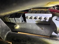
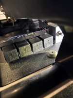
New to me car was previously professionally wired by (schmitty (sp)?) But I do not have any labels or diagrams. Under the back seat there are 4 relays and 5 resettable breakers. I have not had a chance to figure out where they all go, or if there are any blanks (hopefully there is). Fuses are under the dash. currently what is on the car and most likely running through some of the wiring is as follows

-fuel pump
- 16"radiator fans (2) (come on at different temps)
-GPS
-Radio / intercom
-stereo (pretty sure this is direct to battery though as it has a huge inline fuse before the amp)
-light bar
-front bumper lights (2)
-dual whips
-dome light

I think that is all of it....

currently I am adding a trans pump, and intercooler fans. What is the cleanest way to wire these into my current system (if there are no existing blanks) and what should trigger those to come on? The trans pump has the temp sender wired up, so I would assume it will need its own relay and fuse, should the trans pump be triggered off the fuel pump so that it only comes one when the car is running and has reached the 150 degree temp sender limit?. for 2 10" intercooler fans, would those need their own individual relays or just one, and then fuses... should these also be off the fuel pump, or should I tie them to turn on when the first radiator fan kicks on?

Pics below, not the best.
IMG_0700.jpgIMG_0701.jpg
 
I wired my intercooler fans with two separate relays that are triggered by the fuel pump output on my Holley system (it also triggers the fuel pump relay). This wouldn’t work for the trans pump with a temp sensor because it’s a ground signal and the temp sending unit is likely also a ground signal.
 
Hey guys... need some help with this.

New to me car was previously professionally wired by (schmitty (sp)?) But I do not have any labels or diagrams. Under the back seat there are 4 relays and 5 resettable breakers. I have not had a chance to figure out where they all go, or if there are any blanks (hopefully there is). Fuses are under the dash. currently what is on the car and most likely running through some of the wiring is as follows

-fuel pump
- 16"radiator fans (2) (come on at different temps)
-GPS
-Radio / intercom
-stereo (pretty sure this is direct to battery though as it has a huge inline fuse before the amp)
-light bar
-front bumper lights (2)
-dual whips
-dome light

I think that is all of it....

currently I am adding a trans pump, and intercooler fans. What is the cleanest way to wire these into my current system (if there are no existing blanks) and what should trigger those to come on? The trans pump has the temp sender wired up, so I would assume it will need its own relay and fuse, should the trans pump be triggered off the fuel pump so that it only comes one when the car is running and has reached the 150 degree temp sender limit?. for 2 10" intercooler fans, would those need their own individual relays or just one, and then fuses... should these also be off the fuel pump, or should I tie them to turn on when the first radiator fan kicks on?

Pics below, not the best.
View attachment 161043View attachment 161044

The bases of those existing relays are like legos. They interlock with each other. Just go get two more and attach em to the existing ones.

What's the running amp draw of each fan?
 
The bases of those existing relays are like legos. They interlock with each other. Just go get two more and attach em to the existing ones.

What's the running amp draw of each fan?
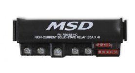
Any idea what brand these are and where I can find them?

Pretty sure each intercooler fan will draw 8 amps.
 
I wired my intercooler fans with two separate relays that are triggered by the fuel pump output on my Holley system (it also triggers the fuel pump relay). This wouldn’t work for the trans pump with a temp sensor because it’s a ground signal and the temp sending unit is likely also a ground signal.
On a standard 5 pin relay with a typical Holley setup (12v+ fuel pump trigger):

85 to the temp switch, (if one wire, if 2 wire, the other side of the switch is grounded)
86 to the fuel pump TRIGGER (piggy back off of the 86 pin on the fuel pump relay)
30 to fuse to battery
87 to the pump

This would ensure that both conditions (temp and engine on) are met for the pump to turn on, and should be electrically safe. If you're running something that turns the fuel pump relay on via ground trigger, you would need a 2 wire temp switch, with the ground trigger wire piggybacked there and the other side to 85. 86 would go to fused battery (either use the same size wire as 30, or run a separate lower-rated fuse for its own circuit, NEVER run a small wire off of a large wire/fuse).

For the intercooler fans, same as above, except I would not run a temp switch. You want the intercooler to act as a heat-sink, not start working when it's hot. One relay per fan, always.
 
On most cars using those style relays (most without switch pros) the relays are for: 1 - Fuel pump, 1 - Ignition, 2 - Fans (one each fan). Your fifth relay might be for the stereo, but if it has an inline fuse then maybe it's for something else. None of those other current circuits would need a relay.

I know that doesn't help with your new additions, but may help identify what's currently there.
 
On a standard 5 pin relay with a typical Holley setup (12v+ fuel pump trigger):

85 to the temp switch, (if one wire, if 2 wire, the other side of the switch is grounded)
86 to the fuel pump TRIGGER (piggy back off of the 86 pin on the fuel pump relay)
30 to fuse to battery
87 to the pump

This would ensure that both conditions (temp and engine on) are met for the pump to turn on, and should be electrically safe. If you're running something that turns the fuel pump relay on via ground trigger, you would need a 2 wire temp switch, with the ground trigger wire piggybacked there and the other side to 85. 86 would go to fused battery (either use the same size wire as 30, or run a separate lower-rated fuse for its own circuit, NEVER run a small wire off of a large wire/fuse).

For the intercooler fans, same as above, except I would not run a temp switch. You want the intercooler to act as a heat-sink, not start working when it's hot. One relay per fan, always.
Considering mine is a MEFI (not Holley) does that change any of the other info you provided in your response?
 
On most cars using those style relays (most without switch pros) the relays are for: 1 - Fuel pump, 1 - Ignition, 2 - Fans (one each fan). Your fifth relay might be for the stereo, but if it has an inline fuse then maybe it's for something else. None of those other current circuits would need a relay.

I know that doesn't help with your new additions, but may help identify what's currently there.
Only 4 relays which makes sense in what you said. But then have the 5 resettable breakers. Gonna try to dig into it a little more tonight to see what we can find.
 
Considering mine is a MEFI (not Holley) does that change any of the other info you provided in your response?
Not sure. You’d have to probe the relay connector to see which one changes state. One is probably constant.

You could also use the output of the fuel pump relay to control the New relays, but that means you have to run bulky wire or an extra fuse to keep things from burning.
 
Traditionally, there are two different types of 12v 5 pin relays.

30 is normally the pin that powers the load. B+

85 & 86 are used to activate the relay. One will have power and one will have ground. You can switch either the power or the ground. It makes absolutely no difference.

Here is the difference between the two relays...

1. 87a will always be connected to 30, untill the relay is activated. When activated, 30 connects to 87.

2. 87a and 87, both connect to 30 when activated.


Style 2, would be the relay you would used for your dual fans. 87 to one fan, and 87a to the 2nd fan.

Use a 30amp relay, and you'll be fine with 2 6 amp draws.

Fuse according. 👍🏼
Inrush will likely be higher than 30a for 2 fans.
 
Traditionally, there are two different types of 12v 5 pin relays.

30 is normally the pin that powers the load. B+

85 & 86 are used to activate the relay. One will have power and one will have ground. You can switch either the power or the ground. It makes absolutely no difference.

Here is the difference between the two relays...

1. 87a will always be connected to 30, untill the relay is activated. When activated, 30 connects to 87.

2. 87a and 87, both connect to 30 when activated.


Style 2, would be the relay you would used for your dual fans. 87 to one fan, and 87a to the 2nd fan.

Use a 30amp relay, and you'll be fine with 2 6 amp draws.

Fuse according. 👍🏼

That's not how it works. You get one or the other.
Being that, your second example would only ever have one fan on at a time.
 
That's not how it works. You get one or the other.
Being that, your second example would only ever have one fan on at a time.
Correctamundo.

1759948065167.png
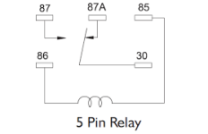
The mechanical switch moves from 87A to 87 when the relay is triggered. 87A is useful for turning things OFF when a trigger condition is met.
 
Correctamundo.

View attachment 161235
The mechanical switch moves from 87A to 87 when the relay is triggered. 87A is useful for turning things OFF when a trigger condition is met.

What you guys don't realize, and what I pointed out earlier, is that there is more than one type of 5 pin relay...

Normally open relay...


Changeover relay ...


There are also additional types of 5 pin relays available (Time delay, diode, etc). So when you are replacing one, make SURE the diagram on the side of the relay, matches the one you are replacing EXACTLY!!
 
Back
Top