Temperature difference between upper and lower radiator outlets

I thought brushless fans work independent of the computer?
Hence why they are wired direct to battery for power and have a sensor in the radiator that detects temperature.
The only switch is an override switch wired to a switch pro or some other switch.
If computer has PWM outputs it can control it with a standard temp sensor input versus the Spal sensor. The Spal sensors have a narrow temperature band, and they are expensive. However, they do allow for basically a standalone install if a car was being retrofitted and didn't have the option in the computer.

If the computer does have PWM outputs, and you know the PWM profile of the fan motor, you can have a broader temp range controlled.

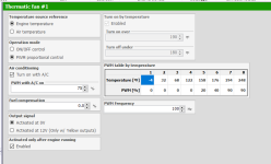
Here is a snip of PWM control in Fueltech for a fan I'm going to use. Most PWM fans don't operate at a percent less than 5, or more than 90. In this case 90% would be the signal for full blast. Some do operate on the inverse where 5% would be full blast...
1761769974451.png
 
See Rock wood's post?

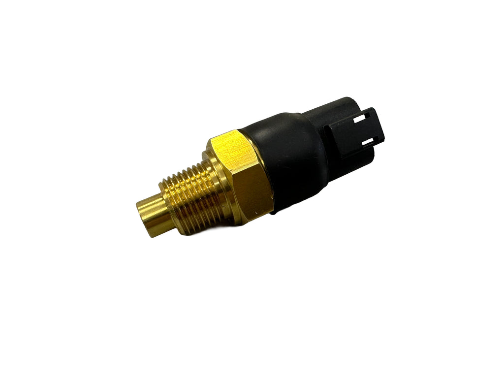
Move the fan temp sensor to the radiator outlet hose.

When I had to do this on a customers car, I had a stainless hose coupler made, with a bung for the fan temp sensor.

These guys made it for me:

Using the cooled side of circuits like this can detrimental, and not optimal. Especially in a circuit that DOES use relays. This can often cause it to cycle more frequently. In some cases it could weld the contacts in the relay from rapid switching.

The HOT side is typically more stable and a true indication of the engines temperature.
 
If computer has PWM outputs it can control it with a standard temp sensor input versus the Spal sensor. The Spal sensors have a narrow temperature band, and they are expensive. However, they do allow for basically a standalone install if a car was being retrofitted and didn't have the option in the computer.

If the computer does have PWM outputs, and you know the PWM profile of the fan motor, you can have a broader temp range controlled.

Here is a snip of PWM control in Fueltech for a fan I'm going to use. Most PWM fans don't operate at a percent less than 5, or more than 90. In this case 90% would be the signal for full blast. Some do operate on the inverse where 5% would be full blast...
View attachment 163366
Thanks for the explanation. All of my buddies that have converted run the fans just like shown on Spal's website, not through a computer.
Learned something new today!!!!
 
Is the Delphi ecu used capable of PWM fan control? Or, is it energizing and deenergizing the override wire at the temps noted above?

Even if the override wire is used as "control", these fans still have a somewhat soft start.
Would still need the controller to send out the PWM signal unless it's just using a built in fail-safe when there's a loss of PWM control? You'd just be wasting all of that brushless magic cycling between full tilt and nothing. If the override is all that's being fed from the relays, that's not enough to melt relays, so something is wrong.

Thanks for the explanation. All of my buddies that have converted run the fans just like shown on Spal's website, not through a computer.
Learned something new today!!!!

The SPAL fans are somewhat non-standard. Not sure what the PWM schema is for those. Most of the OE ones are well known and published.


Lots of reading here.
 
Using the cooled side of circuits like this can detrimental, and not optimal. Especially in a circuit that DOES use relays. This can often cause it to cycle more frequently. In some cases it could weld the contacts in the relay from rapid switching.

The HOT side is typically more stable and a true indication of the engines temperature.

Check your Honda/Toyota/BMW in your driveway, and take note of where the FAN temp sensor is.

There should also be a separate temp sensor that sends the Engine temp to the computer.

Both sensors perform different jobs.

ProTip: Imagine this was a carb engine, with electric cooling fans. Where would you put the fan temp sensor then? 🤔
I know exactly where it is. I didn't say is wasn't done, I just wouldn't recommend it personally.
 
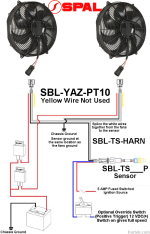
Both fans would come on together with this setup, correct? That's always something i thought should be avoided.


1761776917637.png
 
Both fans would come on together with this setup, correct? That's always something i thought should be avoided.


View attachment 163382
That is correct. I think Spal says you can control 10-12 fans off one sensor.

However, the reason for not doing this with a standard brushed fan is inrush current. One these fans this inrush can be double the operating current. That's tough on your electrical system. Brushless fan start slow and only ran up speed as necessary.
"As necessary" - meaning, that's the magic of that $200 spal sensor - it regulates based on the temperature of the sensor reading, or?
 
answered my own question...pretty cool

 
It was wired with what appeared to be Amazon relays. I have swapped both of the originals out with these that say Omron, but came in a Genuine GM baggie. We’ll see how long these last compared to the chinesenum that have melted. I can’t seem to find literature on thr amperage rating for these relays though.

View attachment 163323
Your relays are failing because they are rated for 20 amps continuous duty.
 
Why are you using relays with SPAL Brushless fans? Those shouldn't be on an on/off, but PWM signal from a controller. The speed should slide from barely on at 185* to full boogie at 201* if that's your scale. Wiring should be direct to battery via adequate fuse/wire (60A and 8AWG min) with the small control wire to the ECM or external controller.

View attachment 163339

Since you're running a radiator with little natural airflow, your fans are going to run a lot. So long as coolant temps are in check, this isn't a concern other than melting relays, but you also shouldn't be running relays.

Also: the bigger the difference in inlet/outlet temps, the hotter the engine is. It's counter-intuitive, but in order for there to be a large difference, the engine has to be hotter. Coolant temps in the engine are quite honestly the only thing that matters unless you're diagnosing a clog or radiator issue.
Well eff me! In the stack of receipts I got with the car they were billed as brushes from the builder in Temecula. Upon inspection they are not brushless and only have two wires coming out.
 
See Rock wood's post?

Move the fan temp sensor to the radiator outlet hose.

When I had to do this on a customers car, I had a stainless hose coupler made, with a bung for the fan temp sensor.

These guys made it for me:

See above re the fans NOT being brushless. Another correction, the coolant temp sensor for the GAGE is in the thermostat housing, the ECM WTS is in the cylinder head. Notably, the gauge is consistent with what the ECM is seeing per HP tuners.
 
See above re the fans NOT being brushless. Another correction, the coolant temp sensor for the GAGE is in the thermostat housing, the ECM WTS is in the cylinder head. Notably, the gauge is consistent with what the ECM is seeing per HP tuners.

I saw. We are learning shit here! 🤣👍🏼

So...

Currently...

Knowing the relay IS powering the fans...

What exactly is activating the relay (currently)? 🤔

*No pun intended* 😁
 
Last edited:
See above re the fans NOT being brushless. Another correction, the coolant temp sensor for the GAGE is in the thermostat housing, the ECM WTS is in the cylinder head. Notably, the gauge is consistent with what the ECM is seeing per HP tuners.
Which model fan do you have? Some SPAL models aren’t intended for constant use.

Also: melted connectors is usually a loose connector. I’d inspect where they plug in closely to make sure nothing is loose.

Other than that: depending on the model fan, those relays might be marginal.
 
first nobody makes a relay worth a shit anymore. just another reason to go solid state but thats a topic for a different discussion.

OP mentioned there is a sender in the water pump, I will bet that is for a gauge and not the ECU temp sender which is typically in the head on LS motors. The ECU sensor controls the fans, not the gauge.

engines like a constant temp. if you have a thermostat, then the thermostat is what really controls engine temp. LS water pumps circulate water through the block, cutting off the flow to the radiator. only once the stat begins to open will cooler water be introduced to the engine.

the point is, if you have a 190' stat and a fan that comes on at 180..........the fan is effectively doing nothing as you are not "full flow" at this point.

if you dont have a thermostat, (keep in mind you must install a block off plate in the water pump to run this way) then your fans are entirely in control of engine temp and will be cycling on and off CONSTANTLY or may never turn off at all.

if your fans are 4 wire brushless you have two options. 1 is to let your ECU send a PWM signal, but i doubt your crude MEFI ecu will do it. the second way is to install a temp sensor wired to the fans.

if you have a thermostat, the correct location for the sensor would be in the head. the fan temp should bring in the fans just below the rated temp of the thermostat. as the temp rises, fan speed will softly increase. both fans should be wired to the same sensor so as to both come on slowly and ramp up if temps climb.

an easy way to tell if you car has a thermostat is how long it takes to warm up. if you have to idle it for 5 minutes to get to temp.....

another way is to feel the radiator right after start up. when the engine is cold, the stat will not allow flow to the radiator. all you have to do is feel the line going to the radiator, if it and the radiator is slowly warming, you have no thermostat.

if someone removed the stat but didnt put the block off plate internally, the circulation through the radiator is about 1/4 of what it would be if the syatem was working properly.
 
Last edited:
Back
Top