Electrician on a Lathe Help (Multimeter Help)

J Alper

Site Sponsor
Joined
Apr 30, 2021
Messages
1,851
Reaction score
1,606
Got a new to me Lathe from Mark @allenoffroad 

Mine is wired for 440V, 

Got a 3 Phase Converter, from North American Rotary,  all hooked up, 

Checked all legs of 3 phase, its making 240V on all 3 legs, 

The Transformer was just buzzing,  Moved one of the wires from 440V to the 220V on the buss bar,  now the light turns on the relay kicks on, but the Contactors are making a loud buzzing noise when you try to flip the lever for the motor to kick in,

Pretty sure i need to move or add another wire from the transformer,  

NOT sure how to use a multimeter on this type of equipment safely,  my use of a multimeter is -- checking 110V, checking 220V, checking the leg of 3 phase with two legs at a time, and checking 12V-DC, 

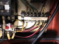
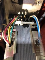
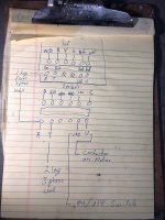
Added some pics of what i am working on
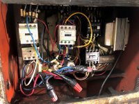
Transformer.jpg  

trans 1.jpg

trans 2.jpg

wire 2.jpg

 
Last edited by a moderator:
What is the coil voltage (nameplate) on the contactors?

 
What is the coil voltage (nameplate) on the contactors?
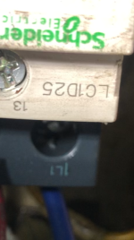
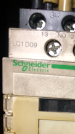
Top Left is the LC1D09

and the Right is the LC1D25,  

I take it i have to move more than one wire on the transformer to make it work for 240V, 

lc1d25.png

lscd09.png

 
Are you saying that the lathe was originally wired for 3 phase 440 volt and now it is connected to 3 phase 240 volt via a phase converter? Just trying to understand what you have going on.

 
i'm not a electrician but i would think you would need to change the transformer. the original is stepping down 440 to 120 or whatever the contactors are rated for to run the controls  if you are cutting the input voltage in half the output would be half as well. unless there is another pole that is for 208 input on the transformer. also the motor will need to be rewired should be a schematic on the motor

 
Are you saying that the lathe was originally wired for 3 phase 440 volt and now it is connected to 3 phase 240 volt via a phase converter? Just trying to understand what you have going on.
Correct was running on 440V 3 phase, picked up the lathe last week,  wired the motor for 240V   from a rotary phase converter,  getting the correct voltage at the converter when i check them in parallel from each leg, 

this is the voltage from the buss bar

going off the far left to right using the status light ground side

w/b is 46.5 volts, R - 240v, Y - 380V G - 440V B/W - 110V W - 0V

When i take the wires off the bottom they read the same
but w/b it was 110V, not sure but when i hooked up the w/b and R it was reading 220v
Followed the two wires and made sure the 3 phase power was 220V each way
but then when i tested the 3phase power coming in off the status light ground one was 46V the other was 194V and the last was 315V, but when i checked them parallel the all read 240V, not sure if that mattered,

So moving the wire marked to from the 440V over to the 220V might not have been correct, when removing the wire T no status light comes on, 

 
i'm not a electrician but i would think you would need to change the transformer. the original is stepping down 440 to 120 or whatever the contactors are rated for to run the controls  if you are cutting the input voltage in half the output would be half as well. unless there is another pole that is for 208 input on the transformer. also the motor will need to be rewired should be a schematic on the motor
some Transformers are 220v/440v, but you might be right,  this has 110V and 220V and 440V coming off it so i think it just needs to me wired correctly,  

 
It also has a LR22 that i will test tomorrow,  that goes to the white U wire on the far right 

 
This is going to be an expensive lesson.

Get a local pro to come out and prevent you from letting a bunch of electrons out.

 
You need to change the way the lathe motor is wired, It should have 12 leads inside the electrical box on the motor. Change it to 230 volt there, should have wiring schematic on the name plate of the motor. then you have to change jumper settings on the transformer for 230 volt.

 
Correct was running on 440V 3 phase, picked up the lathe last week,  wired the motor for 240V   from a rotary phase converter,  getting the correct voltage at the converter when i check them in parallel from each leg, 

this is the voltage from the buss bar

going off the far left to right using the status light ground side

w/b is 46.5 volts, R - 240v, Y - 380V G - 440V B/W - 110V W - 0V

When i take the wires off the bottom they read the same
but w/b it was 110V, not sure but when i hooked up the w/b and R it was reading 220v
Followed the two wires and made sure the 3 phase power was 220V each way
but then when i tested the 3phase power coming in off the status light ground one was 46V the other was 194V and the last was 315V, but when i checked them parallel the all read 240V, not sure if that mattered,

So moving the wire marked to from the 440V over to the 220V might not have been correct, when removing the wire T no status light comes on, 
Multi tap control transformer could have a couple different primary side wiring methods. Is there a nameplate on the transformer? Change your taps on the transformer and if you already rewired the motor to 220 you should be good to go. Need that nameplate or manufacturer at the least.

 
i looked up the number on the contactor it is 110 volt   so being you have 120 v per leg now mabe you dont need a transformer cause 480 v is 277 per leg 

 
I called Webb and they walked me through the process of the transformer, looks like i wired it correctly, they felt the wire was to small,  i upped the wire from the wall and the machine just now, 

Still large buzz but the motor started to move a little when i turned it,  

Checked the power under load at the Phase converter, 

L1 and L2 from the wall under load is 225V,  and  T1 is 238V    T2 is 235V, and the Phase converter T3 is 168V,   pretty low correct,   

 
I would double check your motor wiring sounds like it is single phasing if you have a couple of the wires incorrectly hooked together it will make it not work correctly. I am not a licensed electrician but have worked with 480 three phase on rock crushing plants and Asphalt plants a lot through the years. If I had someone wire a motor incorrectly it raised some havoc. Just a thought 

 
Original-Moggih-Replacement-Magic-Smoke-for-For-Electric-Blasters-Brushed-Flywheeler-1.jpg


will this help? 

 
Last edited by a moderator:
I would double check your motor wiring sounds like it is single phasing if you have a couple of the wires incorrectly hooked together it will make it not work correctly. I am not a licensed electrician but have worked with 480 three phase on rock crushing plants and Asphalt plants a lot through the years. If I had someone wire a motor incorrectly it raised some havoc. Just a thought 
I double checked it but will post it just incase,  someone sent me a picture of there same lathe, with OG wiring, man mine is a little bit of a train wreck, 

 
Since you are using  a lower voltage, amperage to the motor is higher. You need to increase the size of your overcurrent protection located on the load side of the motor contactor.  Is this a three phase motor (3 hots)?

 
Only need to increase overcurrent Protection if it is tripping breaker.  Now overload If the motor's service factor is 1.15 or more, you'll multiply the full load amps by 125% or 1.25 to get the max allowable overload rating in amps. If the motor's service factor is less than 1.15, you'll multiply the full load amps by 115% or 1.15.

 
Only need to increase overcurrent Protection if it is tripping breaker.  Now overload If the motor's service factor is 1.15 or more, you'll multiply the full load amps by 125% or 1.25 to get the max allowable overload rating in amps. If the motor's service factor is less than 1.15, you'll multiply the full load amps by 115% or 1.15.
True. Meant to write overload protection.  :classic_biggrin: :peace:

 
Back
Top