HTElectrical
Active member
- May 6, 2021
- 249
- 90

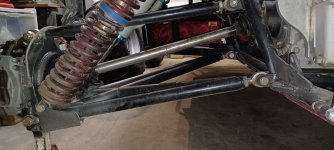
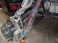
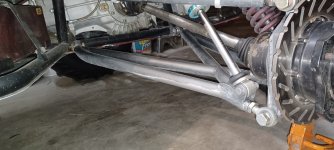
I want to make sure that I am measuring from the correct points. I assume that for D1 it would be from the lower shock bolt straight across to the lower rear Heim. What I am not sure about is where the outer spindle pivot point is or D2.
Does anyone know for sure what they are referring to?
[SIZE=11pt]the motion ratio (MR), which is the ratio of leverage put on the shock depending on where it is mounted on the A-arm. The first thing you do is measure from the lower A-arm pivot point on the chassis to the lower shock mount bolt hole. This we'll call D1 for distance one. Then measure from the same lower A-arm pivot point on the chassis to the outer spindle pivot point. Basically the whole length of the lower A-arm from pivot point to pivot point. This we'll call D2 for distance two. The formula used for motion ratio is D1 divided by D2, then squared. So let's say D1=20 and D2=25. This would be 20/25, or 0.8. Now we square 0.8 (0.8x0.8), which equals 0.64.[/SIZE][SIZE=11pt] [/SIZE]
[SIZE=11pt]angle correction factor, or ACF. For this you will need a scientific calculator, which most home computers have built in. The formula is the Cosine of the angle. So just type in the number of the angle and hit the Cosine button on the calculator. For this article we'll say the shock is at a 10 degree angle. I punch 10 into the calculator, hit Cosine, and it spits out 0.985[/SIZE][SIZE=11pt].[/SIZE]
[SIZE=11pt]The final spring rate (SR) calculation is this: WR (wheel rate) [/SIZE] divided by MRxACF. We already figured out all of these numbers so we just plug them in. This is 62.5 divided by 0.64x0.985, which works out to 62.5 divided by 0.63, and finally, 62.5/0.63 equals 99.2. This is our final spring rate number.


Last edited by a moderator:

